
General guidance for people who work on engines. For exact figures always follow the vehicle or engine maker's workshop manual.
Printable edition
The same guide in the Golden Bearing catalogue format, ready to print and pin up at the workbench.
Download the guide (PDF)Before you start
Most bearing failures are decided before the engine is assembled. Three habits prevent the majority: work clean, measure everything, and follow the engine maker's figures.
What you will need
- Outside micrometer for the journals, and a bore gauge or inside micrometer for the housings
- Calibrated torque wrench (and an angle gauge for bolts tightened by angle)
- Dial indicator with a stand, or feeler gauges, for end float
- Plastigage strips (or the micrometer method) for oil clearance
- Clean engine oil in an oil can, and assembly lubricant
- Lint-free cloths, brushes for the oil passages, compressed air
- New bearings of the right size, new thrust washers, and every bolt, gasket and seal the manual says to replace
- The engine maker's workshop manual for torque, oil clearance and end float figures
Six rules that never change
- Fit new bearings every time. Never reuse old shells.
- Never file, scrape, sand or re-machine a bearing.
- Hold a shell by its edges and keep your fingers off the running surface.
- Keep the back of the shell and its seat clean and dry. Oil the running surface only.
- Tighten to the maker's torque, in the specified order, and replace any bolt the manual says must be replaced.
- Keep every cap in its own position and facing the right way.
Know your bearing
A bearing shell looks simple, but every part of it has a job. Knowing them makes it obvious when a shell is right and when it is not.
- 1Parting face
- 2Locating tab
- 3Wall thickness
- 4Steel back
- 5Running surface
- 6Oil hole
- 7Oil groove
- 8Bearing width
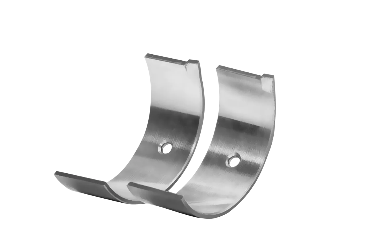
Four common shapes
- Plain half shell the standard main or rod bearing; two halves make one complete bearing.
- Flanged half shell a main bearing with side flanges that also controls the crankshaft's end float.
- Thrust washer a flat half ring (or a pair) that controls end float; its grooved face runs against the crankshaft.
- Bush a rolled sleeve, used in heavy-vehicle engines for the camshaft and the small end of the connecting rod.
How a shell stays in place
Three details decide whether a shell sits properly. Look for each of them every time you fit a bearing.
Out of the engine, the shell is slightly wider across its parting faces than the housing bore. Pushed in, it springs against the wall and stays put while you work.
Each half stands a few hundredths of a millimetre proud of its housing at the parting face. Tightening the cap squeezes that excess away and presses the shell firmly into the housing. That grip carries heat away and stops the shell turning.
The tab must sit in its notch, and the oil hole must lie over the oil passage. If either is off, the shell is wrong or not seated.
Tip Upper and lower halves are often different. The half with the oil hole and groove usually goes in the block; check against the old shells and the manual before you fit.
Inspect before you fit
A new bearing cannot cure a worn or out-of-tolerance part. Measure the crankshaft and the housings first. The limits below are general reference values; where the engine maker gives different ones, use theirs.
| Check | Reference limit |
|---|---|
| Journal diameter | Within the maker's tolerance, measured at several points and in two directions |
| Journal out-of-round | No more than one quarter of the diameter tolerance |
| Journal taper, barrel or hollow, by journal width | Up to 30 mm: 3 µm · 30–50 mm: 5 µm · over 50 mm: 7 µm |
| Surface roughness of journals and thrust faces | Ra 0.2 µm at most |
| Main journal run-out (shaft supported on its end journals) | Neighbouring journals 0.005 mm · whole shaft 0.010 mm |
| Housing bore taper (caps tightened), by width | Up to 25 mm: 3 µm · 25–50 mm: 5 µm · 50–120 mm: 7 µm |
| Housing bore alignment | Neighbouring bores 0.01 mm · whole line 0.02 mm |
| Fillet radii and cracks | Radii exactly as the maker's drawing (too small a radius can crack the shaft); crack-test after straightening, hardening and grinding |
| Stretch bolts | Replace if they have reached the maximum length or minimum diameter, or are damaged |
Tighten the cap to full torque and measure once without shells and once with them. If A and B differ, the cap is offset by half the difference. If the average of A and B differs from C, the bore is not round.
Tip Hardness: a shaft can usually be ground to every undersize without re-hardening, unless its surface was softened by overheating. A nitrided shaft must be nitrided again after grinding.
Prepare the parts
Ten minutes of preparation can save an engine. Do these five things before the first shell goes in.
- Mark and keep the order. Main and rod caps are matched to their positions. Check the position numbers (and the arrows that point to the front) before you take anything apart, and keep each cap with its own housing.
- Clean everything. Brush every oil passage, wash the block, crankshaft, caps and bolts, and blow them dry with compressed air. Wipe the housings with a lint-free cloth. Open the new shells only when you are ready to fit them.
- Make sure it is the right bearing. Put the new shells next to the old ones: same width, same oil holes and grooves, same tab position. Check the size mark against the journal you measured, not against a guess.
- Look at every shell. No dents, burrs or scratches on the back, the parting faces or the running surface. A shell that has been dropped is not fitted.
- Leave the shells as they are. They are made to final size. Do not file, scrape, sand or machine them.
Warning Keep your fingers and brushes off the running surface; whatever sticks to it is pressed between the shell and the shaft when the engine starts.
Fitting main bearings
Work with the block on a stand, upside down if the manual allows. Seat and measure first; lubricate only for the final assembly.
- Seat the upper shells. Push each upper shell into its housing with your thumbs until it snaps home. Start with the end that has no tab, then press the tab end into its notch. Never hammer a shell.
- Check the position. The oil holes must line up with the passages in the block, each tab must sit in its notch, and the shell must lie flat against the housing along its whole width.
- Fit the lower shells and the thrust washers. Seat the lower shells in the caps in the same way, and fit the thrust washers or flanged shell at the position the manual gives. Each cap has its own number and its arrow points to the front.
- Make a trial fit to measure clearance. Lay the clean crankshaft on the dry shells, put a Plastigage strip on each journal and tighten the caps to full torque. Remove them, read the strips and put right any fault before you go on (see “Measuring oil clearance”).
- Lubricate. Wipe off every trace of the strip. Put clean engine oil from an oil can, or assembly lubricant, on the running surfaces of the shells and on the journals; never on the backs.
- Lay the crankshaft in. Lower it gently, without knocking the thrust faces.
- Fit and tighten the caps. Match each cap's number and arrow with the block, oil the bolts if the manual says so, and run them down by hand. Tighten in the stages and order the manual gives, usually from the centre outward. The crankshaft must turn freely by hand after every cap.
- Check end float. With all the caps tightened, measure the crankshaft's end float (see “Thrust washers and end float”).
Tip Before the final torque, push the crankshaft firmly to the front and back once so the thrust faces line up. If the crankshaft binds at any point, stop and find the cause; do not tighten harder.
Fitting connecting-rod bearings
Each rod and cap are a matched pair, and they fit only one way round. Treat the crankshaft journals as carefully as the bearings.
- Identify the pair. Match the number on the rod and its cap, and check which way the rod and piston face (the arrow or mark goes to the front).
- Seat the shells. Fit one shell in the rod and one in the cap, tabs in their notches. The oil hole, if there is one, must match the rod's oil passage.
- Measure the oil clearance. As for main bearings, make a trial fit with dry shells and a Plastigage strip on the journal, then clean away every trace.
- Lubricate. Clean oil on the running surfaces, the journal and the cylinder wall.
- Guide the rod down. Use a ring compressor on the piston, and cover the bolt threads with bolt guards or short pieces of hose so they cannot scratch the journal. Lower the piston until the rod rests on the journal.
- Fit the cap. Match the marks and fit the cap the right way round. Run the nuts or bolts down by hand.
- Tighten. Apply the torque (or torque and angle) the maker specifies, in stages, and replace bolts the manual says are single-use. The crankshaft must still turn freely after each rod.
- Check side clearance. Slide the rod to one side and measure the gap between its big end and the crank web with a feeler gauge.
Warning Never use a bolt that has stretched past the manual's limit, even if it still seems to tighten.
Thrust washers and end float
The crankshaft is allowed to slide a small, measured distance along its axis. Thrust washers or flanged shells set that distance, called end float.
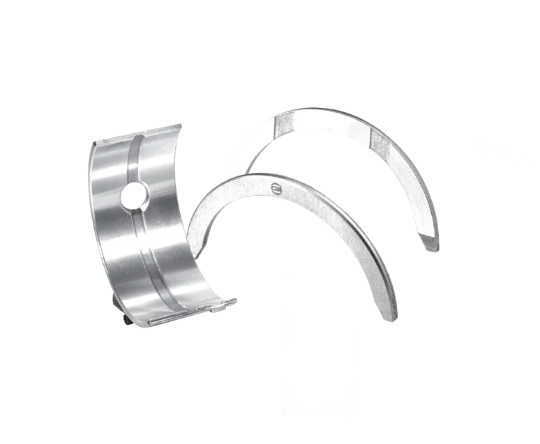
- Fit the washers the right way round. The grooved face goes toward the crankshaft's thrust face; the plain back goes toward the block or cap. Follow any marking such as “block side”, and seat the tab in its notch.
- Fit the crankshaft and tighten the caps. Before the final torque, push the crankshaft to the front and back once so the thrust faces line up.
- Measure. Mount a dial indicator on a stand with its tip on the end of the crankshaft (or on a machined face that moves with it). Push the crankshaft fully to the front and set zero. Push it fully back and read the dial. A feeler gauge between the thrust face and the crank web gives the same figure.
- Compare. The reading must be inside the maker's range. Too little and the thrust faces overheat; too much and the crankshaft hammers back and forth.
Tip If you regrind the crankshaft's thrust faces, grind them to the width the bearing is made for; the end float then comes out right. Finish the thrust faces to the same roughness as the journals.
Measuring oil clearance
Oil clearance is the gap between the journal and the fitted, tightened bearing. Too small and the bearing overheats; too large and oil pressure drops and the engine knocks. Check it on every journal against the maker's figure.
Method 1: with a Plastigage strip
- Fit the shells dry. Wipe the journal and shell free of oil.
- Lay a strip along the journal, a little shorter than the shell and clear of the oil hole.
- Fit the cap the right way round and tighten to full torque. Do not turn the crankshaft.
- Lift the cap straight off, then compare the flattened strip, at its widest point, with the scale on the packet. Wider means tighter.
- Clean every trace of the strip from the shell and journal with a soft cloth.
Method 2: with micrometers
- Fit the shells and tighten the caps to full torque.
- Measure the inside diameter of the fitted bearing with a bore gauge, across the parting face and at the angles used for the bore check.
- Measure the journal with an outside micrometer.
- Subtract: bearing diameter minus journal diameter is the oil clearance.
If the clearance is wrong
- Never file or scrape the shell, or its parting faces, to change the clearance.
- Check the size of the shells, the journal for wear or taper, the housing for distortion, and the seat for dirt.
- A taper shows on the strip as one end wider than the other.
Before the first start
The first seconds are the most dangerous. Until oil reaches every bearing, the surfaces run almost dry. Prime the engine and watch the pressure.
- Final check. Every bolt tightened, every cap in position, nothing left in the crankcase, and the oil pump and pickup fitted as the manual shows.
- Turn it by hand. Rotate the crankshaft several full turns. It must turn smoothly with no tight spot.
- Fill with clean oil. Use the grade the maker specifies, with a new filter.
- Prime the oil system. Spin the oil pump with a pre-lubricator or a drill on the pump shaft, or crank the engine with the fuel or ignition disabled, until oil pressure shows.
- Start and watch. Run at a moderate speed. If there is no oil pressure within a few seconds, switch off at once.
- Run in gently. Avoid full load and high revs at first, follow the maker's running-in advice, check for leaks and the oil level, and change the oil and filter at the first interval the maker gives.
Warning A dry first start can ruin a perfect assembly in seconds.
Common mistakes and what they cause
Most of these show on the old shells. If a new bearing fails early, check this list first.
| Mistake | What happens | How to avoid it |
|---|---|---|
| Dirt on the seat or the back of the shell | The shell cannot seat; it overheats or distorts, and particles score the shaft | Clean every housing; open the shells just before fitting |
| Oil on the back of the shell | Poor grip and heat transfer; the shell can turn | Keep the backs dry; oil the running surface only |
| Tab out of its notch, or shell not seated | The shell turns or digs into the journal | Check seating and tabs before the cap goes on |
| Oil hole not lined up | Oil starvation and overheating | Check the holes against the block passages |
| Wrong size or wrong half | Too tight: seizure. Too loose: low oil pressure and knocking | Measure the journals; compare with the old shells |
| Uneven or wrong tightening; reused stretch bolts | The shell loses its grip and turns, or distorts and wears at one edge | Calibrated wrench, correct order, new bolts where specified |
| Caps swapped or turned round | A misaligned bore loads one edge | Match numbers and arrows |
| Filing or scraping the shell | Wrong dimensions, lost crush, hard debris | Never modify a shell; find the real cause |
| Fitting onto a worn or tapered journal | The new shell wears out early | Measure; regrind to the correct undersize first |
| A dry first start | Surface wear before the oil arrives | Prime the oil system |
Checklist
Tick each box before you move on. Print this page and keep it with the job card.
Before fitting
- Caps and rods marked and in order
- Journals and bores measured and inside the limits
- Everything cleaned; oil passages brushed and blown out
- New shells match the old ones and the journal size
While fitting
- Backs of the shells and their seats clean and dry
- Tabs in their notches; oil holes lined up
- Oil clearance measured on every journal
- Caps matched by number and arrow
- Tightened in stages and in order; crankshaft turns freely
- End float and side clearance within limits
First start
- Oil and filter new and to specification
- Oil system primed; oil pressure confirmed
- No leaks; oil level checked after running
- Oil and filter to be changed at the first interval